What is API 600?
API 600 Standard
API 600 is known as the “Steel Gate Valve Design and Manufacturing Specification.” This standard applies to steel gate valves used in petroleum, natural gas, and related industries, covering the following key aspects:
Design Requirements: API 600 specifies the design criteria for steel gate valves, including structural strength, sealing performance, and corrosion resistance. These requirements ensure that valves can operate reliably in high-pressure and high-temperature environments.
Manufacturing Requirements: API 600 details manufacturing processes, material selection and quality control for valves. Critical components such as valve bodies, bonnets, stems and seats must be constructed of approved materials and go through a rigorous manufacturing process to ensure performance.
Testing and Inspection: In accordance with API 600 standards, valves must pass rigorous testing and inspection before leaving the factory. These tests include pressure tests, leakage tests and visual inspections to ensure that the valves are free of defects and safe to operate.
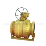
API 600 valves are typically used in large-diameter, high-pressure, and high-temperature applications, such as refineries, chemical plants, and natural gas processing facilities.
What is API 602?
API 602 Standard
API 602 is known as the “Compact Steel Gate Valves and Plug Valves for Refinery Use.” This standard is applicable to small-diameter forged steel gate valves and plug valves, focusing on the following areas:
Design Requirements: API 602 outlines the design standards for forged steel gate valves and plug valves, emphasizing compactness and ease of operation compared to API 600.
The design must ensure effective sealing and stable operation in high-pressure and high-temperature environments.
Manufacturing Requirements: API 602 specifies the materials and manufacturing processes for forged steel valves. These valves must be made from high-strength, high-toughness materials to withstand demanding conditions.
Testing and Inspection: API 602 specifies that a comprehensive testing and inspection program, including pressure and leakage tests, must be performed. These tests are designed to ensure the safe and reliable operation of the valve in actual use.
API 602 valves are suitable for small-diameter, high-pressure, and high-temperature applications such as pipeline systems and high-pressure boilers. These valves are valued for their compact design, robustness, and ease of operation.
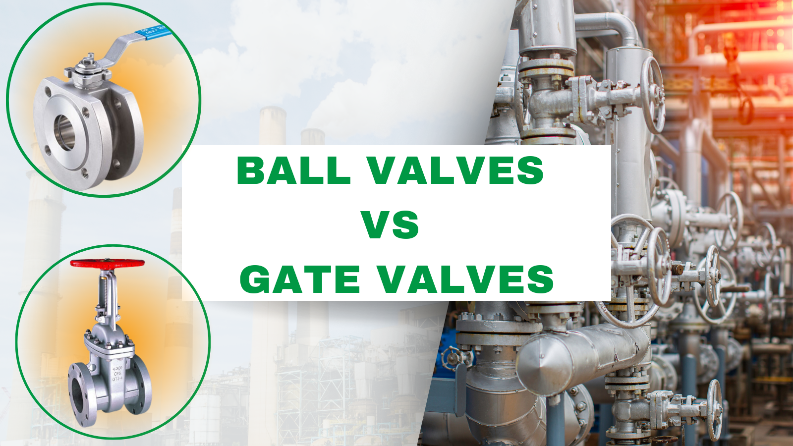
API 600 vs API 602

API 600 and API 602 are both standards set by the American Petroleum Institute (API) for gate valves, but they differ in several key aspects. Below is a detailed comparison based on design differences, temperature rating changes, differences in sealing elements, and differences in application scope.
Design Differences
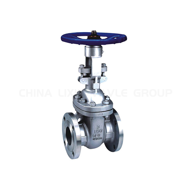
API 600:
- Type: Bolted bonnet steel gate valves.
- Size Range: Typically 2 inches and larger.
- Pressure Ratings: Class 150 to 2500.
- Construction: Heavy wall thickness to handle higher pressures and temperatures.
- Body Materials: Usually carbon steel, alloy steel, stainless steel.
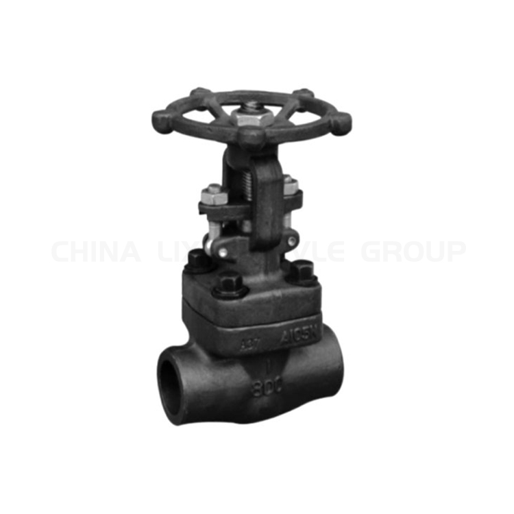
API 602:
- Type: Compact steel gate valves.
- Size Range: Generally 4 inches and smaller.
- Pressure Ratings: Class 150 to 1500.
- Construction: Compact design for lower weight and smaller installation footprint.
- Body Materials: Carbon steel, alloy steel, stainless steel.
Temperature Rating Changes
API 600:
- Designed for high-temperature applications with a wide range of operating temperatures.
- Suitable for temperatures up to approximately 593°C (1100°F) depending on the material used.
API 602:
- Suitable for moderate temperature applications.
- Typically designed for temperatures up to approximately 427°C (800°F) depending on the material used.
Differences in Sealing Elements
API 600:
- Seating: Usually hard-faced with materials like Stellite for better wear resistance.
- Stem Seals: Multiple types available, including packing options like graphite for high-temperature services.
- Backseat: Provides additional sealing and packing replacement while under pressure.
API 602:
- Seating: Often uses elastomeric or metallic seats depending on the application.
- Stem Seals: Limited to fewer packing options compared to API 600, typically suited for lower temperature and pressure applications.
- Backseat: May not always be available or necessary due to lower pressure ratings.
Differences in Application Scope
API 600:
- Typically used in larger, high-pressure, and high-temperature applications like oil refineries, petrochemical plants, and power generation.
- Suitable for critical applications where reliability and longevity are paramount.
API 602:
- Ideal for smaller, moderate pressure and temperature applications.
- Commonly used in utilities, small process applications, and where space and weight are a concern.
Comparison Table
| Aspect | API 600 | API 602 |
|---|---|---|
| Type | Bolted bonnet steel gate valves | Compact steel gate valves |
| Size Range | 2 inches and larger | 4 inches and smaller |
| Pressure Ratings | Class 150 to 2500 | Class 150 to 1500 |
| Construction | Heavy wall thickness | Compact design |
| Body Materials | Carbon, alloy, stainless steel | Carbon, alloy, stainless steel |
| Temperature Range | Up to 593°C (1100°F) | Up to 427°C (800°F) |
| Seating | Hard-faced (e.g., Stellite) | Elastomeric or metallic |
| Stem Seals | Multiple options including graphite | Limited packing options |
| Backseat | Yes | Sometimes |
| Application Scope | Large, high-pressure, high-temp Refineries, petrochemical, power | Small, moderate pressure/temp Utilities, small process |
FAQs on API 600 & API 602
Q1: Can API 602 valves be used in high-temperature applications?
- A: API 602 valves are typically designed for moderate temperatures. For high-temperature applications, API 600 valves are more suitable due to their construction and material specifications.
Q2: What are the key material differences between API 600 and API 602 valves?
- A: API 600 valves use materials capable of withstanding higher pressures and temperatures, while API 602 valves use materials suitable for moderate conditions and compact designs.
Q3: Are API 600 valves more expensive than API 602 valves?
- A: Generally, API 600 valves are more expensive due to their larger size, higher pressure rating, and use of more robust materials. API 602 valves, being smaller and designed for less demanding conditions, are typically less costly.
Q4: How do I choose between API 600 and API 602 valves for my application?
- A: The choice depends on your specific application requirements, including pressure, temperature, space constraints, and industry standards. For high-pressure, high-temperature applications, API 600 is recommended. For compact, moderate conditions, API 602 is more suitable.
Q5: Are there any alternative standards to API 600 and API 602?
- A: Yes, other standards exist for gate valves depending on the application and region. Some examples include ASME B16.34, ISO 10434, and MSS SP-81. However, API 600 and 602 are widely recognized and utilized within the oil and gas industry.
Want To Learn More? Click Here To View Product Details!